
Many design engineers entering the ultraviolet sterilization market rely on standard, theoretical UV LED disinfection calculators to estimate needed dosage. The basic equation seems simple enough:

However, when prototypes undergo laboratory validation, they frequently fail to achieve the required log reduction scores.
The reason is simple: standard equations operate in a vacuum, ignoring complex physical variables like Ultraviolet Transmittance (UVT) in fluids and boundary layer air velocity.
The UVT Bottleneck in Fluid Dynamics
In water purification systems, UVT measures the percentage of light that successfully passes through a 1cm water sample. While distilled water has a UVT of nearly 100%, real-world industrial or commercial wastewater can drop to 70% or lower due to dissolved organic compounds, suspended solids, and iron.
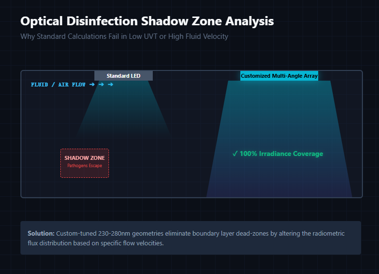
When UVT drops, the ultraviolet energy attenuates exponentially as it moves away from the LED lens. A system designed assuming a 95% UVT will leave major "shadow zones" if it encounters 80% UVT water, resulting in incomplete sterilization.
The Air Velocity Boundary Layer
In air-stream disinfection, high-speed airflow inside HVAC ducts ($2.5 \text{ to } 5.0\,m/s$) creates a turbulent boundary layer around the LED module. Pathogens pass through the irradiation zone in milliseconds. If your optical array doesn't provide uniform power distribution, or if the thermal output of the LED alters the air density around the lens, the effective dosage drops significantly.
To overcome these physical bottlenecks, off-the-shelf, fixed-angle light bars are rarely sufficient. Engineering teams must adapt their optical arrays to the specific fluid dynamics of their system. Utilizing a fully configurable UVC LED 230-280nm full-band customization platform allows developers to adjust viewing angles, increase forward currents, and optimize spatial layouts to guarantee complete, shadow-free disinfection even under the most volatile UVT and high-velocity conditions.